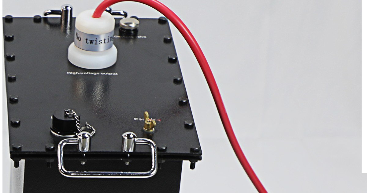
VLF-45TD
The VLF-45TD is a multifunctional VLF hipot test system for installation, acceptance and maintenance testing of 5 kV…
- VLF sine wave output 0 – 45 / 0 – 31.8
- DC output ± 0 – 45
- Output current 0 – 14

30 – 90 kV Very Low Frequency (VLF) AC Hipot Test Sets
Six 30 – 90 kV peak VLF hipot test sets on one split-system platform — choose the voltage rating, keep the same controller, waveform and reporting.
| Specification | VLF-30 | VLF-40 | VLF-50 | VLF-60 | VLF-80 | VLF-90 |
|---|---|---|---|---|---|---|
| Maximum output voltage (peak) kV | 0 – 30 | 0 – 40 | 0 – 50 | 0 – 60 | 0 – 80 | 0 – 90 |
| Output current (peak) mA | 0 – 30 | 0 – 30 | 0 – 30 | 0 – 30 | 0 – 30 | 0 – 30 |
| Output frequencies Hz | 0.1 / 0.05 / 0.02 / 0.01 | 0.1 / 0.05 / 0.02 / 0.01 | 0.1 / 0.05 / 0.02 / 0.01 | 0.1 / 0.05 / 0.02 / 0.01 | 0.1 / 0.05 / 0.02 / 0.01 | 0.1 / 0.05 / 0.02 / 0.01 |
| Duty cycle | Continuous | Continuous | Continuous | Continuous | Continuous | Continuous |
| Measurement accuracy | ± 3 % of reading | ± 3 % of reading | ± 3 % of reading | ± 3 % of reading | ± 3 % of reading | ± 3 % of reading |
| Voltage peak error | ≤ 3 % | ≤ 3 % | ≤ 3 % | ≤ 3 % | ≤ 3 % | ≤ 3 % |
| Controller unit weight kg | 4 | 4 | 4 | 4 | 4 | 4 |
| High-voltage tank (booster) weight kg | 20 | 40 | 40 | 50 | 50 | 55 |
| Operating temperature °C | −10 … +50 | −10 … +50 | −10 … +50 | −10 … +50 | −10 … +50 | −10 … +50 |
| Storage temperature °C | −20 … +70 | −20 … +70 | −20 … +70 | −20 … +70 | −20 … +70 | −20 … +70 |
| Humidity | ≤ 85 % RH | ≤ 85 % RH | ≤ 85 % RH | ≤ 85 % RH | ≤ 85 % RH | ≤ 85 % RH |
All six models share the same controller, output current, frequencies, duty cycle, accuracy and environment ratings — they differ only in maximum output voltage and high-voltage tank weight. Choose the lowest voltage rating whose test level covers the cable classes you test.
| Specification | Value | Unit |
|---|---|---|
| Output | ||
| Output AC voltage (peak, sinusoidal) | 30 – 90 | kV |
| Output current (peak) | 0 – 30 | mA |
| Output frequency | 0.1 / 0.05 / 0.02 / 0.01 | Hz sinusoidal |
| Duty cycle | Continuous | |
| Measurement Accuracy | ||
| Measurement accuracy | ± 3 % of reading | |
| Voltage positive / negative peak error | ≤ 3 % | |
| Mechanical | ||
| Controller unit weight | 4 | kg |
| High-voltage tank (booster) weight | 20 – 55 | kg |
| Design | Two-piece split system (controller + HV tank) | |
| Power Supply & Environment | ||
| Power supply | AC 220 V / AC 230 V, 50/60 Hz, or AC 120 V, 60 Hz | |
| Operating temperature | −10 … +50 | °C |
| Storage temperature | −20 … +70 | °C |
| Humidity | ≤ 85 % RH | |
Control unit of 4 kg plus a high-voltage tank of 20 – 55 kg depending on the voltage rating — a two-piece system handled by two technicians.
Polarity reverses every half cycle like power-frequency AC, giving a space-charge-free stress appropriate for XLPE and EPR insulation.
0.1 / 0.05 / 0.02 / 0.01 Hz let the operator trade test time for reach on high-capacitance cable sections.
Delivers the rated 30 – 90 kV peak output at up to 30 mA peak current on a continuous duty cycle.
The 7-inch touch-screen controller judges results against IEEE 400.2 criteria automatically.
Results are saved internally and printed on site, producing field documentation without an external PC.
Complete test setup, execution and reporting are handled locally from the touch screen.
Periodic VLF proof testing of shielded distribution cable insulation.
Confirming cable circuits and joints after installation or repair work.
Quality verification of new cable installations by contractors and utilities.
Substation bays, manholes and tunnels where a truck-mounted test set cannot reach.
Cable reliability and preventive-maintenance programs.
IEEE 400.2 recommends a test voltage related to the cable's phase-to-earth rating (U0), typically 1.5 to 3 times U0 depending on whether the test is acceptance or maintenance and on cable age. Confirm the target voltage for your specific cable class before testing.
DC testing can leave space charge in cross-linked (XLPE/EPR) insulation that may cause premature failure later. A sinusoidal VLF waveform reproduces the operating AC stress with polarity reversal each half cycle, giving a more realistic and safer test for polymer-insulated cables.
Yes. The 7-inch touch screen controls the full test sequence, interprets results against IEEE 400.2-2013 and prints them on the thermal printer, so no external PC is required in the field.
It is a two-piece split system — a 4 kg controller and a high-voltage tank of 20 – 55 kg depending on rating. Connect the two with the supplied HV lead and the return/earth lead, then program the test from the touch screen.
The VLF-45TD is a multifunctional VLF hipot test system for installation, acceptance and maintenance testing of 5 kV…
The VLF-34TD is a self-contained 34 kV class instrument for installation, acceptance and maintenance testing of 5 kV…