 VA Technology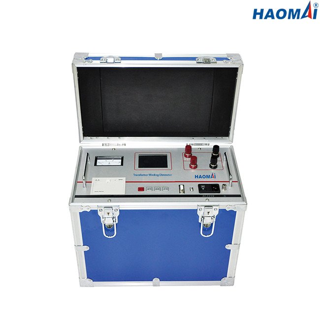
A winding resistance test forces a DC current through a winding, senses the voltage across it and divides. That is the whole measurement. Almost everything that goes wrong with it is a correction that was not applied, or a reading taken before the winding settled.
The value of the test is in the comparison it enables: between phases, between taps, and between this test and the last one. A milliohm reading on its own proves nothing.
Why the test current is high
A transformer winding is an inductive load. When DC is applied, the current rises towards its final value along a time constant set by the winding inductance and resistance, so the measured value drifts until the core reaches a defined magnetizing state. A high test current drives the core there quickly and shortens that settling time.
Current also sets resolution. A rated 100 A winding has very little resistance in absolute terms, so a large current produces a larger, easier to measure voltage across it. The TWO-1100S offers user-selectable DC test currents of 100 / 50 / 20 / 10 / 5 A, covering 30 µΩ to 4 Ω with ±0.2 % reading ± 2 µΩ accuracy and 0.1 µΩ resolution. Each current has its own measuring range, and the reading is only valid inside it.
Temperature is the correction that decides pass or fail
Copper resistance rises with temperature. Two readings of the same winding taken at different temperatures are not comparable, and a winding tested warm will look worse than the same winding tested cold. IEC 60076-1 and IEEE C57.12.90-2015 both require the measured resistance to be referred to a common reference temperature before it is compared with anything.
That means recording the winding temperature at the time of the test, and allowing for the heating the test current itself produces in the winding. Where the comparison is against a previous test, the previous figure has to be corrected the same way. A deviation that survives the correction is real; one that does not was a temperature difference.
Measuring every tap, and reading the pattern
Winding resistance is measured across the full tap range, for the same reason a ratio test is: the tap changer is the part most likely to be wrong, and its faults are specific to a step. The shape of the deviation points at the cause.
| Deviation pattern | Where to look first |
|---|---|
| One tap high, its neighbours normal | Selector or diverter contact at that step |
| Deviation grows across the range | Winding or tap-section fault, not one contact |
| One phase differs from the other two | A problem in that phase winding |
| All three phases move together | Usually the measurement: temperature, settling time or lead contact |
That last row is the one that matters most in practice. A uniform shift across all three phases is rarely three simultaneous winding faults.
Mistakes that look like a winding fault
- Recording the reading before the inductive settling has finished, which leaves it high and drifting.
- Using a two-wire connection, which adds test-lead and contact resistance to a milliohm result. The 4-wire (Kelvin) method used by the TWO-1100S separates the current and sense leads so their resistance is excluded.
- Selecting a test current whose measuring range does not cover the winding’s resistance.
- Comparing a new winding resistance test against an old one without referring both to the same temperature.
- Disconnecting the leads while the winding is still storing magnetic energy, which is both a measurement error and a safety hazard.
Frequently asked questions
What does a winding resistance test detect?
It detects anything that changes the resistance of the current path: a tap-changer contact not making properly, a broken strand or shorted turn in a winding, a poor connection at a bushing or a bolted joint, and, for rotating machines, a fault in a field or armature winding. It also establishes the baseline the next test is compared against.
Why is my winding resistance reading still drifting?
The winding is still settling. Inductance keeps the current rising for a time after the test begins, and the display follows it. Increase the test current within the winding’s rating to shorten the settling time, and wait for the value to stabilise before recording it.
Why is the reading higher than the nameplate or the last test?
Check temperature first, then the connection. A winding measured warm reads higher than the same winding measured cold at the same condition, and a two-wire connection adds lead resistance. Only after both are excluded is a genuine increase worth investigating.
The winding resistance test sits alongside the other electrical checks on a transformer. VA-TEK builds the transformer testers family for that work: the TWO-1100S for winding resistance, the TTR-400 for turns ratio and vector group, the TDC-3100 for insulation power factor and the FRA100 for sweep frequency response. The turns ratio testing article covers the tap-by-tap companion measurement, and transformer differential protection testing covers the protection side. Send the winding schedule, the tap positions and the test current you intend to use through the contact form.
Sources: IEC 60076-1, Power transformers — Part 1: General (measurement of winding resistance and referral to a reference temperature). IEEE C57.12.90-2015, Test Code for Liquid-Immersed Distribution, Power and Regulating Transformers (DC winding resistance measurement). TWO-1100S product data (vendor data).