 VA-TEK Engineering
 Transformer Electrical Testing: A Practical Guide
Transformer condition assessment combines electrical measurements, oil chemistry and visual inspection. Each electrical test answers a different question, and together they reveal winding integrity, core condition and insulation ageing. This guide covers the tests every commissioning and maintenance engineer should understand.
1. Turns Ratio and Vector Group (TTR)
The turns ratio test verifies that the ratio of primary to secondary turns matches the nameplate for every tap position, and confirms the vector group and polarity. It is the fastest way to detect shorted turns, open windings and incorrect tap connections. Modern automatic instruments measure all taps in a single sequence and compare the results directly against nameplate values.
2. Winding Resistance
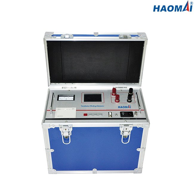
DC winding resistance measurement detects loose connections, broken strands and contact problems in tap changers. Results should be compared phase-to-phase and against previous tests; a deviation above 2% between phases warrants investigation. Measurements on large transformers require a stabilized DC current to overcome winding inductance before a valid reading can be taken.
3. Sweep Frequency Response Analysis (SFRA)
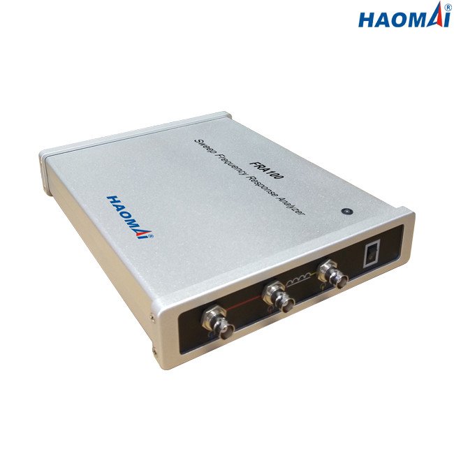
SFRA compares the impedance signature of a transformer against a reference trace to detect winding deformation, displacement and core movement. Because it is a comparative test, a good factory baseline is essential — which is why the measurement is taken before and after transport, and again after any through-fault event.
4. Insulation Resistance and Polarization Index
Insulation resistance tests (IEEE 43) detect moisture, contamination and insulation degradation in windings and bushings. The polarization index — the ratio of the 10-minute to the 1-minute resistance — indicates whether the insulation is dry and free of contamination. A value below 2.0 on a dry transformer indicates a problem.
5. Excitation Current
Excitation current testing detects core problems such as shorted laminations and residual magnetism. Comparison between phases and against the factory value reveals core damage that ratio and resistance tests alone cannot find.
6. Insulation Power Factor / Dissipation Factor
Measuring the power factor of the insulation system detects moisture, contamination and ageing across bushing and winding insulation. Trending over time is far more valuable than any single reading — a steadily rising power factor is a reliable indicator of progressive insulation deterioration.
Integrated Testing Strategy
Electrical tests are most valuable used together as a programme:
- Baseline at factory acceptance — ratio, winding resistance, excitation current and insulation tests before the transformer leaves the works
- Post-transport — repeat ratio, winding resistance and SFRA against the factory baseline to detect shipping damage
- Commissioning — a full electrical test programme plus protection relay verification before energization
- Periodic maintenance — insulation resistance, polarization index and power factor to trend insulation ageing
- After a through-fault — SFRA and ratio to confirm no winding displacement has occurred
Oil chemistry remains a valuable complement to electrical testing. Transformer oil and dissolved-gas analysis is provided by our sister brand PAS DGA (pasdga.com) on the same manufacturing floor.
Related Equipment and Reading
Each test above maps to one instrument:
- TTR-400 — Transformer Turns Ratio Meter (ratio and vector group, section 1)
- TWO-1100S — Transformer Winding Ohmmeter (DC winding resistance, section 2)
- FRA100 — Sweep Frequency Response Analyzer (SFRA, section 3)
- TDC-3100 — Tan Delta and Capacitance Tester (insulation power factor, section 6)
- Transformer Testers — the complete family
Oil chemistry is the other half of the picture: PAS DGA dissolved-gas analysis reports the fault gases that electrical tests cannot see.
This article was prepared by the VA-TEK engineering team. For more information about our transformer test instruments, visit our Products page or contact us.