 VA Technology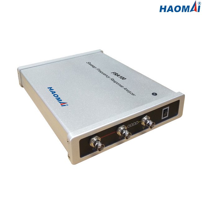
No single test proves a transformer is fit to energize. Transformer commissioning tests work as a sequence: each step narrows what the next can conclude, and the measurements taken with direct current change the state of the core for every magnetic test that follows.
Run the order wrong and a healthy transformer can fail a check that never measured the transformer. One rule matters most: the DC tests go last.
What transformer commissioning tests are for
Commissioning sits between factory testing and energization. The transformer has been shipped, possibly opened, and connected on site, so the question is not whether it was built correctly but whether anything changed on the way to the substation.
The sequence builds a chain of evidence. A ratio reading means little if the insulation has not first been shown to be sound, and a sweep frequency response fingerprint means little unless it is compared with one taken before the core was disturbed.
The sequence, in order
| Order | Test | What it establishes |
|---|---|---|
| 1 | Visual and wiring inspection | The transformer is wired and connected correctly |
| 2 | Insulation resistance | Winding-to-earth and winding-to-winding insulation condition |
| 3 | Turns ratio at every tap | Winding integrity, tap-changer wiring, vector group |
| 4 | Insulation power factor and capacitance | Moisture, contamination and ageing per insulation element |
| 5 | Sweep frequency response | Core and winding mechanical condition against a baseline |
| 6 | Winding resistance at every tap | Contact, joint, strand and turn resistance |
Turns ratio is checked at every tap, not only at nominal: the tap changer is the part most likely to be wrong and its faults belong to individual steps. The TTR-400 covers a 0.9 to 10000 ratio range with automatic vector-group identification, so a wrong tap or a reversed connection shows as a stepwise deviation from the nameplate.
Insulation power factor and capacitance follow: insulation that has taken in moisture or aged shows a higher loss. The TDC-3100 measures dissipation factor and capacitance with UST, GST and GSTg connections, so each element — bushing, winding or CVT — is judged alone.
Why the DC tests come last
Winding resistance is measured with direct current, and DC magnetizes the core. That state stays behind after the leads are removed. A sweep frequency response trace depends on the core’s magnetic state, so a trace taken after a DC test can differ from its baseline for a reason that has nothing to do with the winding.
So take every AC measurement first and leave winding resistance to the end. If a magnetic measurement must be repeated afterwards, demagnetize the core first. The FRA100 is compared against a factory or pre-transport baseline, a second reason to sweep early. It sweeps from 10 Hz to 10 MHz and loads up to nine curves for comparison.
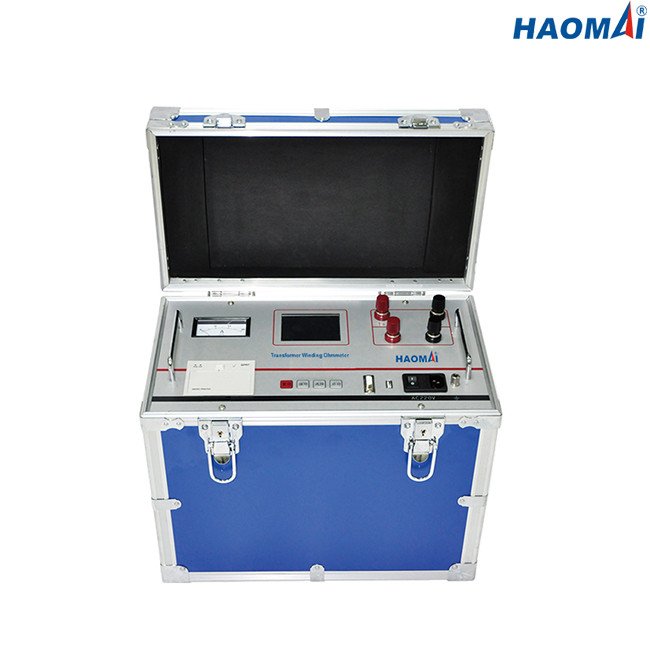
The TWO-1100S is built for that last slot: a four-wire Kelvin connection with selectable currents from 5 A to 100 A, covering 30 µΩ to 4 Ω, with an automatic discharge when the test ends. Waiting is part of the procedure — a winding still holding magnetic energy is both a measurement error and a hazard.
Reading the results as a set
No single number is a verdict. The sequence lets each result be read against the others: a ratio deviation that moves with tap position, a capacitance that has risen since the last test, a winding resistance uniformly high across all three phases. A uniform shift across phases is almost always a measurement condition — temperature, or a DC reading taken before the winding settled — not three simultaneous faults.
That is why a record of transformer commissioning tests should carry the conditions, not only the readings: winding temperature at the time of the DC test, the tap positions covered, the test voltage used, the baseline each sweep trace was compared against, and the instrument serial numbers.
Frequently asked questions
Which commissioning tests need a baseline?
Sweep frequency response is the clearest case: the trace means nothing on its own, so it is compared with a factory, sister-unit or pre-transport reference. Insulation power factor and winding resistance are similar in a weaker sense — read against the nameplate, a previous test or the other phases rather than a fixed pass mark.
Can winding resistance be measured first?
It can, but the DC current leaves the core magnetized, and that residual state affects the magnetic tests that follow. If winding resistance is done early, the response trace taken afterwards should be treated with suspicion unless the transformer is demagnetized first.
In what order should the taps be tested?
Every tap, for both the ratio and the winding resistance test, from one end of the range to the other. Covering all positions of both lets the two results be lined up step by step, which is what exposes a fault belonging to a single diverter position.
In short, transformer commissioning tests are a chain — inspection, insulation resistance, ratio, insulation power factor, sweep frequency response, then winding resistance and discharge — and the order carries as much information as the readings. VA-TEK builds the transformer testers family for that chain. The turns ratio testing and winding resistance testing articles go deeper on two of the steps. Send the transformer rating, the tap range and the required tests through the contact form.
Sources: IEC 60076, Power transformers (ratio and winding-resistance test requirements). IEEE C57.12.90-2015, Test Code for Liquid-Immersed Distribution, Power and Regulating Transformers. TTR-400, TDC-3100, TWO-1100S and FRA100 product data (vendor data).